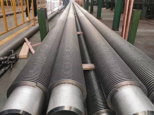
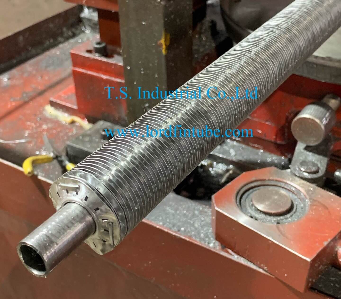
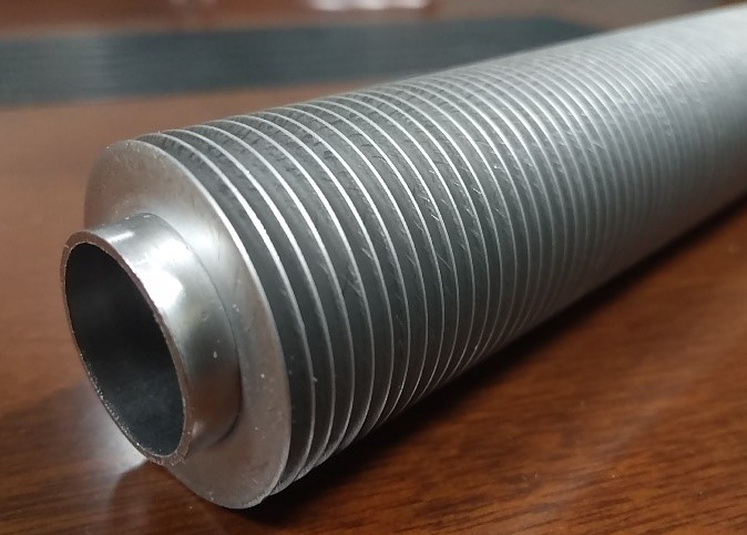
Tubes de condenseur et déchangeur de chaleur ASTM A1012 avec ailettes intégrées
Spécification standard ASTM A1012 pour les tubes de condenseur et déchangeur de chaleur en acier ferritique, austénitique et duplex sans soudure et soudés avec ailettes intégrées
1. Portée de la norme ASTM A1012
1.1 Cette spécification décrit des tubes en acier allié ferritique, austénitique et duplex sans soudure et soudés sur lesquels la surface externe ou interne, ou les deux, a été modifiée par un processus de formage à froid pour produire une surface intégrale améliorée pour un transfert de chaleur amélioré. Les tubes sont utilisés dans les condenseurs de surface, les évaporateurs, les échangeurs de chaleur et les appareils de transfert de chaleur similaires dans des diamètres dextrémité sans ailettes allant jusquà 1 po (25,4 mm inclus). Les tubes de chaudière sont exclus.
1.2 Les valeurs indiquées en unités pouces-livres doivent être considérées comme la norme. Les valeurs données entre parenthèses sont à titre dindication seulement.
1.3 La mise en garde suivante ne concerne que la partie relative à la méthode dessai : Section 12 de cette spécification : Cette norme ne prétend pas répondre à tous les problèmes de sécurité, le cas échéant, associés à son utilisation. Il incombe à lutilisateur de cette norme détablir des pratiques de sécurité et de santé appropriées et de déterminer lapplicabilité des limitations réglementaires avant lutilisation.
2. Documents référencés ASTM A1012
2.1 Normes ASTM :
Spécification A 213/A 213M pour les tubes sans soudure en acier allié ferritique et austénitique pour chaudières, surchauffeurs et échangeurs de chaleur2
A 249/A 249M Spécification pour les tubes soudés en acier austénitique pour chaudières, surchauffeurs, échangeurs de chaleur et condenseurs2
Spécification A 268/A 268M pour les tubes en acier inoxydable ferritique et martensitique sans soudure et soudés pour service général2
Spécification A 269/A 269M pour tubes en acier inoxydable austénitique sans soudure et soudés pour usage général2
Spécification A 450/A 450M pour les exigences générales relatives aux tubes en acier au carbone, en alliage ferritique et en acier allié austénitique2 Spécification A 688/A 688M pour les tubes de chauffe-eau dalimentation en acier inoxydable austénitique soudés2
Spécification A 789/A 789M pour les tubes en acier inoxydable ferritique/austénitique sans soudure et soudés pour le service général
Spécification A 803/A 803M pour les tubes de chauffe-eau dalimentation en acier inoxydable ferritique soudés2
A 941 Terminologie relative à lacier, à lacier inoxydable, aux alliages apparentés et aux ferroalliages2
E 1316 Terminologie des examens non destructifs3
3. Terminologie ASTM A1012
3.1 Définitions – Pour la définition des termes généraux utilisés dans cette spécification, reportez-vous à la spécification A 941.
3.2 Symboles (nomenclature des tubes à ailettes intégrales) :
D = diamètre extérieur de la section non renforcée
Di = diamètre intérieur de la section non améliorée
dr = diamètre de racine de la section améliorée à lextérieur du tube
do = diamètre extérieur de la section améliorée di = diamètre intérieur de la section améliorée W = épaisseur de paroi de la section non améliorée Wf = épaisseur de paroi de la section améliorée
Fh = hauteur de laileron – section améliorée à lextérieur du tube
Fm = épaisseur moyenne des ailettes — section améliorée à lextérieur du tube
P = pas moyen des nervures – section améliorée à lintérieur du tube Rh = hauteur de la nervure – section améliorée à lintérieur du tube Ha = angle dhélice de la nervure – section améliorée à lintérieur du tube Tt = cône de transition
4. Informations de commande ASTM A1012
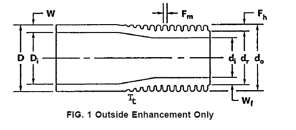
FIG. 1 Amélioration extérieure uniquement
4.1 Il incombe à lacheteur de spécifier toutes les exigences nécessaires pour le matériel commandé dans le cadre de cette spécification. Ces exigences peuvent inclure, sans toutefois sy limiter, les suivantes :
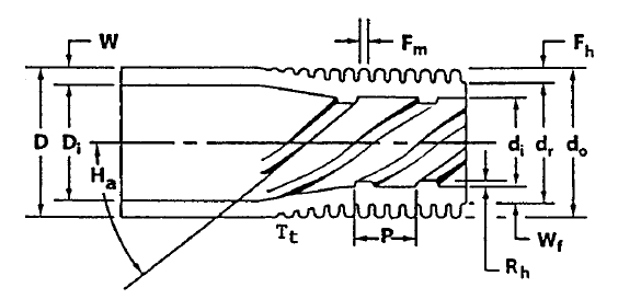
FIGUE. 2 Amélioration extérieure et intérieure
4.1.1 Désignation ASTM et année d’émission (cette spécification) ;
4.1.2 Désignation ASTM et année de délivrance (spécification du tube simple) ;
4.1.3 Soudé ou sans soudure ;
4.1.4 Nuance d’alliage et désignation UNS ;
4.1.5 Dimensions ; diamètre extérieur du tube lisse, épaisseur de la paroi du tube lisse (moyenne ou minimum spécifiée), longueur et emplacement des surfaces non renforcées et longueur totale du tube. La configuration des surfaces renforcées (ailettes par unité de longueur, hauteur des ailettes, épaisseur de la paroi sous lailette, pas des nervures, hauteur des nervures, etc.) doit être convenue entre le fabricant et lacheteur (voir les figures 1 et 2).
4.1.6 Revenu (à ailettes ou recuit de détente);
4.1.7 Quantité ;
4.1.8 Emballage ;
4.1.9 Essais non destructifs ;
4.1.10 Inspection du client ;
4.1.11 Rapport dessai du broyeur ;
4.1.12 Attestation.
5. Exigences générales ASTM A1012
5.1 Le matériel fourni dans le cadre de cette spécification doit être conforme aux exigences applicables de la spécification A 450/A 450M, sauf indication contraire dans les présentes.
5.2 Les sections améliorées (intégralement à ailettes) du tube doivent être produites par formage à froid du tube de telle manière que les ailettes extérieures, la paroi sous lailette et les nervures intérieures (lorsque spécifié) soient homogènes.
5.3 Les tubes décrits par cette spécification doivent être fournis avec des extrémités non améliorées (simples).
5.4 Les sections améliorées du tube sont normalement fournies dans létat « à ailettes » (état écroui produit par lopération damélioration). Les sections non améliorées du tube doivent être à létat recuit et doivent être adaptées aux opérations de rodage.
6. ASTM A1012 Materials and Manufacture
6.1 The integrally enhanced (finned) tubes shall be manufactured from seamless, welded, or welded/cold worked plain tubes that conform to one of the following ASTM specifications: A 213/A 213M, A 249/A 249M, A 268/A 268M, A 269/ A 269M, A 688/A 688M, A 789/A 789M, A 803/A 803M.
7. ASTM A1012 Temper
7.1 The tube after enhancing shall normally be supplied in the as-finned temper. When specified by the purchaser, for bending, coiling or other fabricating operations, enhanced portions of the tube may be stress relief annealed or solution annealed.
7.2 Heat treatment of enhanced sections, or bend areas, or both, shall be in accordance with the governing plain tube specification.
8. ASTM A1012 Chemical Composition
8.1 The tubing specified shall conform to the chemical requirements prescribed in the governing plain tube specifica- tion.
9. ASTM A1012 Tensile Requirements
9.1 The tube prior to the finning operation, or unenhanced portions of the finned tube, shall conform to the requirements for tensile properties prescribed in the governing plain tube specification.
10. ASTM A1012 Permissible Variations in Dimensions
10.1 Diameter—The outside diameter of the unenhanced sections shall not exceed the diameter tolerances shown in the governing plain tube specification as measured by micrometers and verified by “go” and “no go” ring gages. The diameter over the enhanced sections shall not exceed the diameter of the plain sections involved, as determined by a “go” ring gage unless otherwise specified. The dimensions of the ring gages shall be as described in 10.1.1 and 10.1.2.
10.1.1 The inside diameter dimension of the “go” ring gage shall be equal to the nominal tube diameter, plus the maximum tolerance, plus .002 in. The length of the “go” ring gage shall be 1 in. (25.4 mm) minimum.
10.1.2 The inside diameter dimension of the “no go” ring gage shall be equal to the nominal tube diameter minus the maximum tolerance. The length of the “no go” ring gage shall be 1 in. (25.4 mm) minimum.
10.2 Wall Thickness—The wall thickness of enhanced and unenhanced sections shall not exceed the thickness tolerances shown in the governing plain tube specification unless other- wise agreed to between the manufacture and purchaser. No tube at any point shall be less than the minimum thickness specified in the plain sections or in the enhanced sections.
10.3 Length—The length of the tubes shall not be less than that specified, but may exceed the specified value by the amounts given in Table 1.

10.3.1 The length of plain ends, as measured from the tube end to the first tool impression, shall not be less than that specified, but may exceed the specified value by 1⁄2 in. (12.7 mm).
TABLE 1 Length Tolerances
Specified Length, ft (m) Tolerance, in. (mm) Up to 24 (7.3), incl + 1⁄8 (3.2)
Over 24 to 34 (7.3 to 10.4), incl + 1⁄4(6.4)
Over 34 to 44 (10.4 to 13.4), incl + 3⁄8(9.5)
Over 44 (13.4) + 1⁄2 (12.7) max
10.3.2 The length of fin sections and lands (unenhanced portions) shall be as specified 6 1⁄4 in. (6.35 mm).
10.4 Squareness of Cut—The angle of cut of the end of any tube may depart from square by not more than 0.016 in.
10.5 Straightness—The tube shall be reasonably straight and free of bends or kinks.
11. ASTM A1012 Workmanship, Finish and Appearance
11.1 Finished tubes shall be clean and free of foreign material, shall have smooth ends free of burrs, and shall be free of injurious external and internal imperfections. Minor defects may be removed, provided the dimensional tolerances of Section 10 are not exceeded.
11.2 A slight amount of oxidation on the surface resulting from heat treatment after enhancing or bending is acceptable. When the plain tube specification allows for a slight amount of oxidation on the surface resulting from heat treatment, this also is acceptable.
12. ASTM A1012 Nondestructive Tests
12.1 After enhancing operations, subject each tube to a nondestructive electromagnetic test, and either a pneumatic or hydrostatic test as specified in the purchase order. Tubes normally shall be tested in the as-fabricated condition but, at the option of the manufacturer or purchaser, may be tested in the stress relief annealed condition.
12.1.1 Eddy Current Test—Eddy current inspect the tube by passing it through an encircling coil designed to test the entire cross section of the tube.
12.1.1.1 The reference standard used to adjust the sensitivity setting of the apparatus shall be sound and of the same nominal alloy, enhanced configuration, condition (temper), and nominal dimensions as the lot of tubes to be tested on a production basis. Drill four holes not larger than 0.031 in. (0.787 mm) in diameter radially through the enhanced wall in each of four successive planes at 0°, 90°, 180°, and 270°. Use enhanced and unenhanced areas is not less than the minimum specified.
12.1.1.5 Tubes causing relevant signals because of injurious defects (incomplete welds, splits, embedded debris, broken tool impressions, ID defects), that reduce the wall thickness below the minimum specified shall be rejected. If, after retest and examination, no source for the reject signal can be discerned, the tube shall be rejected.
12.1.2 Pneumatic Test—When examined with this test method, each tube shall withstand a minimum internal air pressure of 250 psi (1.72 MPa), for a minimum of 5s, without showing evidence of leakage. The test method used shall permit easy detection of any leakage either by placing the tube underwater or by using the pressure differential method as follows:
12.1.2.1 Air Underwater Pressure Test—Each tube shall be tested in accordance with Specification A 450/A 450M except using test pressure specified in 12.1.2.
12.1.2.2 Pressure Differential Test—Procedure and acceptance criteria shall be agreed upon between the manufacturer and purchaser.
12.1.3 Hydrostatic Test—When examined with this test method, each tube shall be tested in accordance with Specification A 450/A 450M, except, the equation for calculating test pressure shall be modified as follows:
Inch2Pound Units: P 5 32 000 Wf / dr
SI Units: P 5 220.6 Wf / dr
where:
P = hydrostatic test pressure, psi (or MPa), Wf = wall under fin thickness, in. (or mm), dr = fin root diameter, in. (or mm),
12.1.3.1 As agreed upon between the manufacturer and purchaser, a minimum hydrostatic test pressure in excess of the requirements of Specification A 450/A 450M may be stated on the order. The tube wall stress shall be determined by the following equation:
a suitable drill jig to guide the drill, taking care to avoid distortion of the adjacent fins. Locate one hole in the weld for welded material. Space artificial discontinuities at least 16 in.
where: S 5 Pdr / 2Wf
(406 mm) apart to provide signal resolution adequate for interpretation. Discard and replace the reference standard when erroneous signals are produced from mechanical, metallurgical, or other damage to the tube.
12.1.1.2 Adjust the eddy current test unit to obtain an optimum signal-to-noise ratio with the minimum sensitivity required to detect all four artificial defects in the reference standard on a repeatable basis. Equipment adjustments and tube speed maintained during calibration shall be the same for production tubes.
12.1.1.3 Set aside tubes showing an eddy current indication in excess of any signal obtained from artificial defects in the reference standard and subject them to retest or rejection.
12.1.1.4 Tubes causing irrelevant signals because of debris and like effects shall be considered to conform, should they not cause output signals beyond acceptable limits when retested. Tubes causing irrelevant signals because of visible and identifiable handling marks (rough fin tip, notches in the fin) shall be considered to conform, provided the wall thickness in the
S = tube wall stress, psi (or MPa), and all other symbols as defined in 12.1.3.
12.1.3.2 The hydrostatic test may be performed before the tube is cut to final length but must be performed after enhancing, bending, heat treatment, or other forming operations.
13. ASTM A1012 Inspection
13.1 The manufacturer shall inspect and make the necessary tests to verify that the enhanced tubes furnished conform to the requirements of the customer purchase order and to the requirements of this specification.
13.2 Should the purchaser additionally elect to perform his own inspection, the manufacturer shall make provisions for such in accordance with requirements specified in Specification A 450/A 450M.
14. ASTM A1012 Rejection
14.1 Provisions for rejection shall be in accordance with requirements in Specification A 450/A 450M.
15. ASTM A1012 Certified Test Report
15.1 The manufacturer shall furnish to the purchaser a certified test report in accordance with requirements specified in A 450/A 450M.
15.2 In addition, the certified test report shall include the following information and test results, as modified, when applicable:
15.2.1 Plain Tube:
15.2.1.1 ASTM material designation.
15.2.1.2 Welded or seamless.
15.2.1.3 Alloy grade and UNS designation.
15.2.1.4 Tube dimensions (outside diameter and wall thick- ness).
15.2.1.5 Heat number.
15.2.1.6 Heat analysis.
15.2.1.7 Product analysis, when specified.
15.2.1.8 Tensile properties.
15.2.1.9 Flattening test acceptable.
15.2.1.10 Reverse flattening test acceptable.
15.2.1.11 Flaring test acceptable.
15.2.1.12 Flange test acceptable.
15.2.1.13 Hardness test values.
15.2.1.14 Hydrostatic or pneumatic test pressure and test results.
15.2.1.15 Non-destructive electric test method and test re- sults.
15.2.1.16 Impact test results.
15.2.1.17 Other test results or information required to be reported by the product specification.
15.2.1.18 Test results or information required to be reported by supplementary requirements, or other requirements desig- nated in the purchase order shall be reported, but may be reported in a separate document.
15.2.2 Enhanced Tube:
15.2.2.1 ASTM material designation.
15.2.2.2 Manufacturer name and order number.
15.2.2.3 Customer name and purchase order number.
15.2.2.4 Product description or part number.
15.2.2.5 Quantity.
15.2.2.6 Eddy current test results.
15.2.2.7 Pneumatic test pressure and test results, when specified.
15.2.2.8 Pression d’essai hydrostatique et résultats d’essai, lorsque spécifiés.
15.2.2.9 Recuit de détente des contraintes, lorsque spécifié.
15.2.2.10 Résultats de tous autres contrôles ou tests exigés par le bon de commande du client.
16. ASTM A1012 Emballage et marquage des emballages
16.1 Le tube doit être emballé conformément à la pratique standard du fabricant, sauf accord contraire entre le fabricant et lacheteur et indiqué dans le bon de commande.
16.2 Chaque unité dexpédition doit être marquée lisiblement avec le nom du fournisseur, le nom du client, ladresse dexpédition, le numéro de bon de commande, la désignation de lalliage, la taille ou le numéro de pièce, la longueur du tube et le nombre de pièces.
17. Mots-clés de la norme ASTM A1012
Tube en acier allié 17.1 ; Acier inoxydable austénitique; tubes en acier au carbone; tube de condenseur ; acier inoxydable duplex; tubes de chauffe-eau dalimentation; acier inoxydable ferritique/austénitique ; acier inoxydable ferritique ; tube échangeur de chaleur; applications à haute température ; tube en acier sans soudure; tubes en acier inoxydable; Tube en acier; tube de surchauffeur ; applications de service à température élevée ; tube dacier soudé
Liens de téléchargement de la norme ASTM A1012/A1012
TéléchargerFiles/File/2023121013070872.pdf
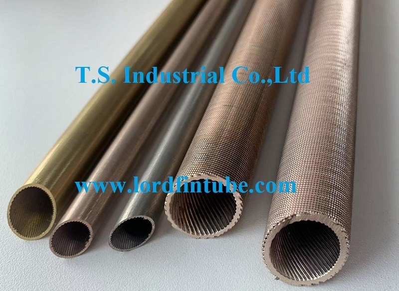
Tubes de condenseur et déchangeur de chaleur ASTM A1012 avec ailettes intégrées
请输入搜索关键字
确定

